

More surge protection is not automatically better. A building management system may not need a separate surge protective device at every point if existing protection, bonding, grounding, and the connected device’s voltage threshold provide an appropriate level of protection. The decision should reflect the actual risk to each circuit, not simply add devices everywhere.
It’s understandable to want to protect controllers, sensors, and communications from damaging voltage spikes, especially when failures can disrupt building operations. This guide explains when surge protection for building management systems (BMS) may be unnecessary at a particular point, and how equipotential bonding, grounding, and device voltage thresholds inform that decision. You’ll also see why requirements can differ between power and low-voltage communication circuits, helping you assess protection without relying on a one-size-fits-all approach.
Key Takeaways
- Protection needs can differ across power, control, data, and communication lines, so assess the exposure of each circuit rather than treating the BMS as one unit.
- Local bonding and effective grounding help limit voltage differences and give surge energy a path to earth.
- Compare a device’s voltage threshold with the protection strategy around it; the right decision depends on the equipment and circuit.
- For broader power continuity and quality needs, consider where Uninterruptible Power Supplies (UPS) and Harmonic Analysis fit into the picture.
When Might You Not Need Surge Protection?
A building management system can coordinate HVAC, lighting, fire alarms, access control, elevators, energy meters, and security systems across a facility. ISO 16484 uses the term building automation and control system (BACS). A centralized design processes monitoring and control logic at one point, while distributed controllers assign functions to separate subsystems.
A transient voltage surge is a brief voltage spike. It can damage controllers, sensors, power supplies, and communication systems, disrupting functions such as access control or HVAC monitoring. Protection needs vary by circuit: power lines supply panels, while control and data lines carry signals. If a system already has coordinated protection, it may not need an additional device at every endpoint. The exposure and sensitivity of each connected component matter.
In the United States, applicable electrical-code requirements depend on the code adopted for the project and the local authority having jurisdiction. The facility’s location and system design determine which provisions apply; no single code identifier covers every BMS installation.
Protection is commonly installed at the building service entrance and at panels supplying BMS equipment, including control panels. Low-voltage control, data, and communication lines may also need protection, particularly where they enter a building or connect to exposed equipment. Protecting only the power supply can leave a sensor or communications path vulnerable. Conversely, when suitable upstream and circuit-level protection are already coordinated, another device at a particular endpoint may add little. Consider the line type, the connected device’s voltage threshold, and the existing protection path. A control panel powering a critical subsystem deserves particular attention because a surge there can affect multiple connected components.
Earthing, grounding, and equipotential bonding
Earthing and grounding provide a path for surge current to dissipate, while equipotential bonding reduces dangerous voltage differences between conductive parts. In a BMS, this distinction matters: a surge protective device can divert excess voltage to earth, but poor grounding can undermine that path. Electrical engineering should account for both the device connection and the facility’s grounding arrangement.
Bonding connects conductive parts so they stay closer to the same electrical potential during a surge. Without effective bonding, a voltage difference can develop between a controller enclosure and nearby network equipment. Current may then travel through communication wiring or connected components, increasing the risk of damage or failure. A sound bond helps limit that difference, but it does not replace surge protection.
Local bonding of network surge protection can be considered for each BMS subsystem to help maintain communications. For example, a protection device serving an HVAC controller should bond to the HVAC subsystem’s local reference rather than rely on a distant connection. This keeps the protection path close to the equipment it serves. Separate lighting or access-control networks may need their own coordinated arrangements.
Operationally, assess the full path: the surge protective device, its earth connection, the bonded equipment, and the incoming power or signal line. A long or poorly connected path can reduce how effectively surge energy is diverted. Local bonding also helps avoid voltage differences between interconnected panels. A UPS can support continuity during supply interruptions, but it doesn’t replace grounding, bonding, or surge protection. Explore Uninterruptible Power Supplies as a separate part of power continuity planning.
Surge protective device voltage thresholds
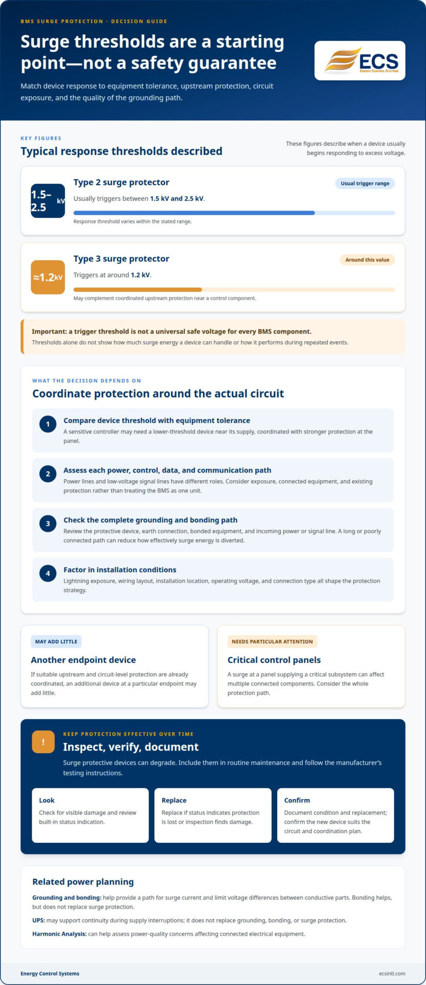
A surge protective device’s voltage threshold helps indicate when it begins responding to excess voltage. A Type 2 surge protector usually triggers at 1.5 kV to 2.5 kV, while a Type 3 surge protector triggers at around 1.2 kV. Those figures describe device response, not a universal safe voltage for every BMS component.
Choose protection by comparing the device threshold with the connected equipment’s voltage tolerance and the upstream protection. For example, a sensitive controller may need a lower-threshold device near its supply, coordinated with stronger protection at the panel. Thresholds alone do not show how much surge energy a device can handle or how it performs during repeated events. Lightning exposure, wiring layout, and installation location also shape the protection strategy.
Inspection and replacement matter because surge protective devices can degrade over time. Include them in routine maintenance: look for visible damage, review any built-in status indication, and follow the manufacturer’s testing instructions. Replace a device if its status shows it can no longer protect the circuit or an inspection identifies damage. Document its condition and replacement, then confirm the new device suits the circuit and its coordination plan.
Mechanical fit is only one part of installation. A device must also match the circuit’s operating voltage, connection type, and required response threshold. A Type 3 device near a control component may complement upstream protection, but it shouldn’t be treated as a substitute for a coordinated system. Review the thresholds and replacement plan as part of your facility’s power continuity planning. Discuss power continuity needs.
Energy Control Systems
Energy Control Systems can help you consider how power continuity and power quality affect building operations alongside surge protection decisions. If a BMS depends on uninterrupted power for monitoring or control, an Uninterruptible Power Supply (UPS) may be relevant to continuity planning. Harmonic Analysis can help assess power-quality concerns that may affect connected electrical equipment.
These offerings address related power needs, not the design of surge protection itself. Consider them when reviewing how supply interruptions or electrical power quality fit into your facility’s wider operational risks. A clearer view of those needs can help you make informed decisions about the systems your building relies on.
For help assessing your facility’s power needs, contact Energy Control Systems.
Make the Next Power Decision With Confidence
Turn your findings into a facility-specific plan. Map the BMS circuits and the operational loads they support, then document where protection decisions depend on equipment sensitivity, power continuity, or power quality. This gives your team a clear basis for prioritizing next steps instead of adding devices without a defined purpose.
For broader power-protection planning, Energy Control Systems offers comprehensive solutions, alongside Uninterruptible Power Supplies (UPS) and Harmonic Analysis. These offerings address related power needs and do not replace an assessment of your BMS protection requirements.
For help considering your facility’s power needs and surge protection for building management systems (BMS), contact Energy Control Systems. A considered next step can make the plan clearer and help your team move forward with confidence.
Frequently Asked Questions
What is surge protection for building management systems (BMS)?
Surge protection for BMS uses protective devices and coordinated design to limit transient voltage reaching BMS circuits. The goal is to reduce the chance that a brief electrical disturbance interrupts building controls. For example, protection may be considered where a controller connects to both a power supply and an external sensor, since each connection creates a potential path into the equipment.
Which BMS components and communication lines need surge protection?
Consider the paths connecting exposed equipment to sensitive electronics, not just the main power feed. A rooftop HVAC sensor, an outdoor access-control reader, and a controller linked to a remote panel each have different wiring routes and exposure. Map their power, signal, and network connections, then prioritize circuits whose failure could interrupt monitoring or essential building functions.
What types of surge protective devices (SPDs) are used for BMS power, Ethernet, RS-485, and field wiring?
Available SPD technologies include gas discharge tubes, metal oxide varistors, silicon avalanche diodes, and hybrid devices. They differ in response and surge-handling characteristics. The line determines the suitable device: a power SPD is not automatically suitable for Ethernet, RS-485, or field wiring. Match the protector to the circuit’s electrical characteristics and communication requirements to avoid disrupting normal signals.
How do you select an SPD’s voltage rating, clamping voltage, and surge current rating for BMS circuits?
Start with the circuit’s normal operating voltage and the connected equipment’s tolerance. The SPD’s voltage rating must suit the circuit, while its clamping voltage indicates the level it allows through during a surge. Its surge-current capability should suit the exposure and protection position. For example, a panel-entry device and protection near a sensitive controller may serve different roles in a coordinated design.
How do grounding, bonding, and cable routing affect BMS surge protection?
Grounding gives diverted surge current a path, while bonding helps limit voltage differences between connected metalwork. Both depend on sound connections near the protected subsystem. Cable routing matters too: where practical, avoid routing signal cables alongside likely surge-current paths, and keep connections to protection devices short and direct. For example, a local controller bond can reduce voltage differences across interconnected panels.

Article by
Jeff Edwards
Founder of ECS International Inc. Edwards travels and speaks extensively in Latin America, Asia and Africa on the subject of power quality; transients and mitigating their impact on profitability. After graduating from Texas Tech University in Lubbock Texas, Edwards spent 9 years in the Telecommunications sector prior to founding Energy Control Systems in 1987 as a Texas based corporation selling surge suppression and UPS systems. The company has evolved into a global power quality products and energy efficiency concern with operations spanning South America, Asia, Europe and Africa.
Disclaimer
Some of the above information may be the opinion of the author.