

An SPD’s label isn’t the whole protection story: connection wires can add voltage during a surge. For BS 7671-based installations, the total applicable SPD connection path shouldn’t exceed 1.0 m. The spd wiring length rules matter because longer connections increase inductance and can raise the voltage that reaches protected equipment.
It’s easy to focus on the device rating and overlook the cable path. Yet even a correctly selected SPD may provide less effective installed protection if its leads are unnecessarily long. Short, direct connections help limit the additional voltage.
This guide explains how cable length affects installed protection, what the 0.5 m and 1.0 m figures mean in context, and how to measure the complete connection path. You’ll also see why bends, loops, and conductor layout matter, so you can assess the installation with greater confidence.
Key Takeaways
- Long SPD leads add inductance, which can raise the voltage seen by protected equipment during a surge.
- Keep connections short and direct; bends and loops can add to the wiring’s inductive effect.
- Measure the applicable connection path by tracing the conductors between the SPD and its connection points, including each lead section.
- Separate the SPD’s surge-protection role from backup power needs when planning resilience for critical equipment.
How Does Cable Length Change the Installed Protection Level?
Longer SPD leads add inductive voltage during a surge, increasing the clamping voltage seen by the protected circuit. Short, direct connections help the SPD deliver its intended protection to connected equipment. Applying the spd wiring length rules helps you assess the installed protection, rather than relying only on the device’s declared rating.
Lead Length and SPD Performance
Lead length is the conductor distance between the SPD terminals and their connection points. Longer conductors can increase the voltage remaining across the protected circuit during a surge, even when the SPD’s declared rating is unchanged. This difference matters when assessing installed protection. Keep the path direct and avoid excess wire that could reduce the protection reaching equipment. These spd wiring length rules emphasize the wiring as well as the device.
Inductance and Surge Voltage
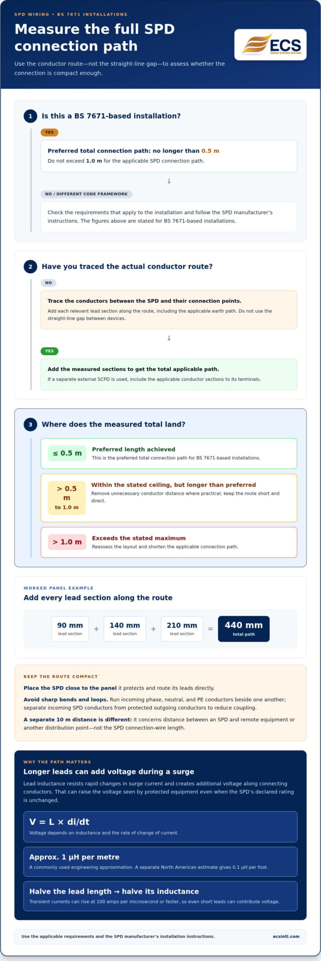
Lead inductance resists rapid changes in surge current and creates additional voltage along connecting conductors. A commonly used engineering approximation is 1 μH per metre; a separate North American estimate gives 0.1 μH per foot. The relationship is expressed as V = L x di/dt. Since transient currents can rise at 100 amps per microsecond or faster, even short leads can contribute voltage. Halving lead length halves its inductance.
VPR is the clamping voltage measured after a surge test using a 6kV 1.2/50us, 3kA 8/20us combination waveform. UL specifies a standard 6-inch lead length for testing and releasing an SPD’s VPR. This is a test condition, not a universal installation limit. IEC 61643-11:2025 covers requirements and test methods for AC low-voltage SPDs. Use the correct connection layout for the circuit and follow the manufacturer’s instructions.
The effect of cable length on installed protection level
Long connections can add voltage during a surge, reducing the protection equipment experiences. Keep the SPD close to the panel it protects, and route its leads directly. A separate 10 m concept concerns distance between an SPD and remote equipment or another distribution point. That distance is not the SPD connection-wire length.
Wire size matters, but short connections matter more for SPD performance. A commonly recommended connection is #10 AWG stranded wire or larger between the SPD and breaker panel. The manufacturer’s installation instructions determine the correct connection details for the specific device. Avoid sharp bends and loops; arrange conductors to limit coupling between incoming surge current and protected outgoing conductors.
For hard-wired SPDs, use an appropriately rated circuit breaker rather than connecting directly to the panel’s main lugs. If breakers are impractical or unavailable, a fused disconnect switch can provide the connection and facilitate servicing. Grounding and bonding must also meet the electrical requirements for the installation.
What conductor gauge and wire type are required? A commonly recommended choice is #10 AWG stranded wire or larger. Follow the manufacturer’s instructions for the SPD and installation.
Do rules vary by state or local electrical code? Yes. Applicable requirements depend on the NEC edition and amendments adopted locally. Older references cite Article 285; newer NEC editions organize overvoltage protection under Article 242.
For a broader view of electrical conditions affecting equipment, review power-quality considerations alongside SPD placement and wiring.
How Is the SPD 0.5 m Connection Length Measured?
For BS 7671-based installations, the total applicable SPD connection path should preferably be no longer than 0.5 m. Use the spd wiring length rules to assess the actual conductor route, not the straight-line gap between devices. Include the relevant SPD connections and earth path in the applicable total.
A worked panel example totals 440 mm: lead sections of 90 mm, 140 mm, and 210 mm. Add each section along the connection path. Where a separate external SCPD is used, account for the applicable conductor sections to its terminals. The protective-device arrangement changes the route, not the need to keep conductors short.
Type 1, Type 2, and Type 3 SPDs don’t have one universal connection-length figure for every installation. For BS 7671-based installations, use the preferred 0.5 m total and do not exceed 1.0 m. Follow the applicable requirements and manufacturer instructions for the SPD type and setup. The shortest practical panel layout places the SPD near the panel, with direct connections. These spd wiring length rules help distinguish the measured path from other cable distances.
If the preferred length is difficult to achieve, first remove unnecessary conductor distance. Avoid sharp bends and loops, which increase inductance. Where suitable, a close nipple and direct wires to the first breaker at the panel top can support a compact layout. Run incoming phase, neutral, and PE conductors beside one another, and separate incoming SPD conductors from protected outgoing conductors to reduce coupling. Connect protected outgoing feeders to the external SCPD or SPD terminals, as applicable.
Careful routing supports voltage protection. For related power-quality considerations, consider how electrical conditions affect the wider installation.
Energy Control Systems: Uninterruptible Power Supplies (UPS)
Energy Control Systems offers Uninterruptible Power Supplies (UPS) for facilities that need backup power during interruptions. An SPD addresses transient overvoltage, while a UPS serves a different purpose. Considering both helps distinguish surge protection needs from continuity needs for sensitive equipment.
If equipment issues persist beyond surge events, Harmonic Analysis can help assess harmonic conditions in the electrical system. This insight can inform power-quality decisions alongside SPD placement and wiring. A UPS may be relevant when the concern is maintaining power during an interruption rather than limiting surge voltage.
For support with power protection and continuity needs, contact Energy Control Systems or visit ecsintl.com.
Make the Next Power-Protection Decision With Confidence
Good protection planning involves more than one device. Consider how surge exposure, power quality, and continuity needs interact across your facility, then prioritize the equipment and processes that matter most. Applying the spd wiring length rules is one part of a clearer electrical protection plan, not a substitute for considering the wider system.
Energy Control Systems offers advanced surge suppression series designed to meet diverse facility requirements. Their relevance depends on the protection needs you’re addressing. A focused conversation can help you explore these options alongside your facility’s power-quality priorities.
Contact Energy Control Systems to discuss your next power-protection step. A thoughtful plan can help you move forward with greater confidence.
Frequently Asked Questions
How Should an SPD Be Positioned Inside a Distribution Board?
Position the SPD close to the panel conductors it protects, while keeping incoming surge conductors separate from protected outgoing conductors. Run incoming phase, neutral, and PE conductors beside one another to reduce loop area. Where metal enclosure parts are present, routing conductors against them can also reduce the frame-loop surface. Keep the board layout clear and direct.
How much performance change will the lead length cause on an SPD?
The change depends on conductor length and surge-current rise, so there isn’t one fixed amount for every installation. As an illustration, one estimate places an SPD’s VPR at 680 volts with 10-inch leads, compared with 600 volts using 6-inch leads. Longer leads can increase an SPD’s voltage protection level, so keep connections short and direct. These figures illustrate why test ratings and installed performance can differ.
What If the SPD Connection Cannot Be Kept Within 0.5 m?
For BS 7671-based installations, treat 0.5 m as the preferred total connection path and keep the applicable path within 1.0 m. First look for a more direct route or a closer mounting position. Also distinguish the SPD connection wires from the separate 10 m concept for distance to remote equipment or another distribution point. They describe different cable paths.
What if I cannot trim the lead length to 6 inches?
A 6-inch lead length is a UL test condition for releasing an SPD’s VPR, not a universal installation limit. Follow the device’s installation instructions and keep leads as short and direct as the panel layout allows. Twisting SPD leads may help reduce VPR, though the effect depends on the installation.
Why Must SPD Connection Cables Be Short?
Short cables reduce connection inductance and the extra voltage produced as surge current rises. A commonly used approximation is 1 μH per metre, and transient currents can rise at 100 amps per microsecond or faster. Since additional voltage follows V = L x di/dt, reducing conductor length limits the voltage added between the SPD and the protected circuit.

Article by
Jeff Edwards
Founder of ECS International Inc. Edwards travels and speaks extensively in Latin America, Asia and Africa on the subject of power quality; transients and mitigating their impact on profitability. After graduating from Texas Tech University in Lubbock Texas, Edwards spent 9 years in the Telecommunications sector prior to founding Energy Control Systems in 1987 as a Texas based corporation selling surge suppression and UPS systems. The company has evolved into a global power quality products and energy efficiency concern with operations spanning South America, Asia, Europe and Africa.
Disclaimer
Some of the above information may be the opinion of the author.